
Worldwide shipping
Shipping & Returns
Quality assured
Find retail locations
Expert support
For All Your Questions
Fast and secure
For All Your Questions
Shipping & Returns
Find retail locations
For All Your Questions
For All Your Questions
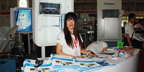
In case we have not met, I’m Alexa Williams, Ask Alexa. I have worked here at Etelux for almost 15 years establishing great relationships with our customers and partners. Throughout my career at Etelux, I have had the pleasure of advocating for you, the customer, to make sure that you are taken care of. Most of the time, I am the friendly voice that answers the corporate phone line, so if we have not met in person, I’m sure we have talked. This form is to reach me directly, and I will respond as soon as I can. You can ask me anything, such as questions about our enclosures, help with which replacement parts to order, certification questions, etc…
Serving the Chinese scientific industry for over 15 years, discover how quality products, competitive pricing, and next day delivery allow us to achieve our mission “Enabling Technology for a Better World ".
Ultricies eu consectetur vitae donec scelerisque ante a ut morbi aptent tincidunt est non sagittis ut.


Shipping & Returns
Find retail locations
For orders above $100
For All Your Questions
No account yet?
Create an Account